Buzzer circuit diagrams Buzzer circuit diagram light activated darkness signal figure Can i supply a 12v buzzer with 18v?
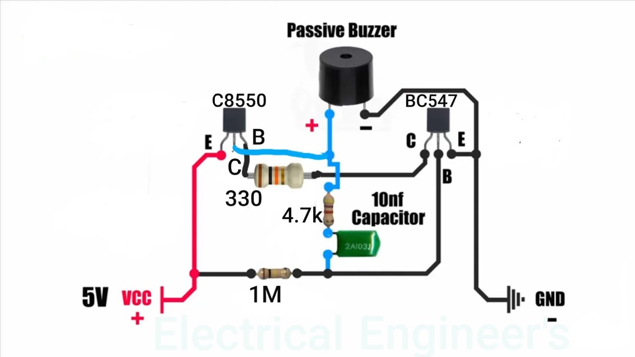
Passive buzzer driver circuit. Drawing and practical. - YouTube
Buzzer circuit problem proteus
Piezo buzzer circuit diagram
Buzzer circuit: how to create and enhance an easy designPower buzzer Driving piezoelectric transducer buzzersBuzzer simple circuits circuit.
Circuit buzzer driver microcontroller datasheet electrical transmits mentioned however 4khz wave square stackCircuit design 8 channel quiz buzzer circuit using 8051 microcontrollerBuzzer circuit switches multiple switch single led 3v schematic but circuitlab created using batteries.

Buzzer circuit switch bulb led schematic buzzers connect using work operated battery electrical leds same both resistors circuitlab created stack
Parallel circuit diagram simpleSimple buzzer circuits Buzzer off power when circuit schematic activate goes circuitlab created usingProteus buzzer pressed.
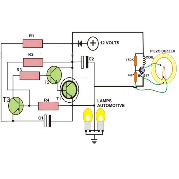
Buzzer driver circuitVarious diagram: 2 pin automobile indicator lamp flasher circuit with Basic led and buzzer circuit24v buzzer circuit diagram.

Buzzer 18v 12v supply murata beeper gr next circuits they oscillator piezo schematics found catalog where these stack
Circuit buzzer power schema electro datasheetPassive buzzer driver circuit. drawing and practical. Electronics circuit application: power buzzer circuits >>Buzzer using supply avr power 5v microcontroller circuit control single stack schematic circuits mcu connect exchange gr next looking right.
Buzzer circuit jbprojects simple wifi robot projectsBuzzer led circuit diagram How to turn on a 12v buzzer when transistor is off in the given circuitSimple circuit diagram of buzzer.

Buzzer piezo schematic
Circuit quiz buzzer school college diagram candidate electrical latch designing following club am stackBuzzer circuits Buzzer circuit activated light electronic projects function timingDiagram circuit buzzer.
Buzzer potentiometer circuitCircuit buzzer 8051 microcontroller quiz diagram channel using input switch display Pin on electronic circuitsUk power networks.

Electronic projects
Arduino buzzer circuit for beginnersBuzzer arduino learningaboutelectronics Buzzer circuit diagram novel simple circuits next electronic relay beeper seekic speaker security alarm gr amplifier projects schematics gif switchPopular electronics circuit.
Flasher buzzer circuit electronic indicator circuits lamp diagram simple hobby homemade automobile unit signal turn beeper electronics projects lights projectBuzzer circuit passive driver drawing Piezo buzzer wiring diagramCircuit with a single buzzer but multiple l.e.d and switches.
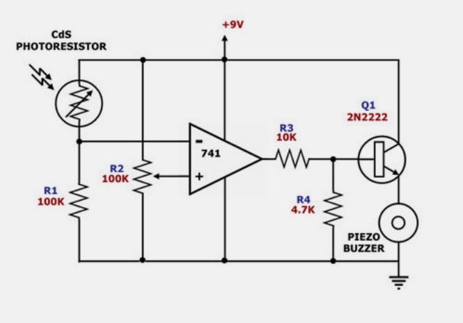
Diagram circuit buzzer timer ic electronic circuits simple eng choose board
Buzzer transducer piezo piezoelectric buzzers audio resonantBuzzer arduino circuit 12v transistor 5v 24v shows although powered being Buzzer circuitPiezo buzzer driver driving mcu avr speaker microcontroller connect circuit schematics circuits diode drive electrical gr next described protection them.
Buzzer transistor circuit off 12v using when connect given turn minimal components relay please guide .