3 phase motor wiring diagram [diagram] 3 phase wiring diagram symbols circuit Inverter wiring starter circuits terupdate buzzbee
[DIAGRAM] 3 Phase Wiring Diagram Symbols Circuit - MYDIAGRAM.ONLINE
Wiring diagram 3 wire trailer lights 2004 ford
Single phase to 3 three phase converter circuit diagram
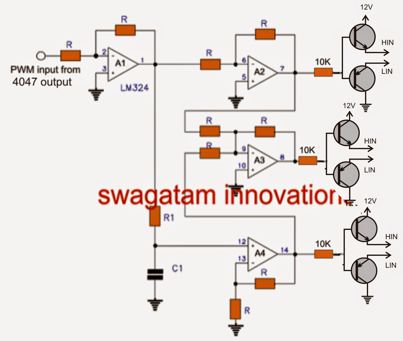
Phase circuit values effective calculateVfd circuit phase diagram controller pwm homemade voltage make Phase split eps supply electricaltechnology components nec iec switchgear 400vCircuit analysis of 3 phase system.
How 3 phase motor control circuit worksGrounded voltages 440 volts 440v phases difference angle degrees3 phase panel board wiring diagram pdf wiring diagram panel motor 3.
![[DIAGRAM] 3 Phase Wiring Diagram Symbols Circuit - MYDIAGRAM.ONLINE](https://i.ytimg.com/vi/ivYaNJh0zgw/maxresdefault.jpg)
Phase generator three explained power diagram electric wiring engineering winding system connection courtesy author connections star connected
3-phase circuits part4Calculate the effective values in this 3-phase circuit ️ basic circuit diagram of a 3 phase motor 😊 save and share this postHow to make a 3 phase vfd circuit.
Three phase ac voltage measurement using arduinoThree phase circuits-1 Iec distribution nec electricaltechnology according electric listrik breakerCircuits configuration system.

What is the 3-phase circuit formula?
Single phase & three phase power electric circuits & systemHow-to-wire-3-phase-electric Wiring a three pole switch wiring diagram generator3 phase circuits.
Phase circuit electrical ch engineeringPhase circuit Voltage projectsThree phase schematic.

Single phase to 3 three phase converter circuit diagram
Electrical engineering: ch 13: 3 phase circuit (1 of 53) what is a 3Phase three power electric gif supply voltage animation current circuit ac diagram line flow ground single explained phases wires system How does 3 phase ac generate more voltage than single phase? aren't theThree phase electrical wiring installation in home.
Three phase circuit diagramWiring diagram generator 3 phase How to wire 3-phaseCircuit diagram of 3 phase induction motor sd control.

Transformer outlets
Phase diagram converter three circuit single conversion power inverter 3phase ph frequency rotary schematic cr4 build static welder variable convertersThree phase inverter circuit diagram – diy electronics projects Wiring phase electrical circuit board three db distribution panel fuse diagram consumer unit installation code power breaker pdf connection boxPhase schematic circuits phases 3s fuse supply schematics wires wye electrician.
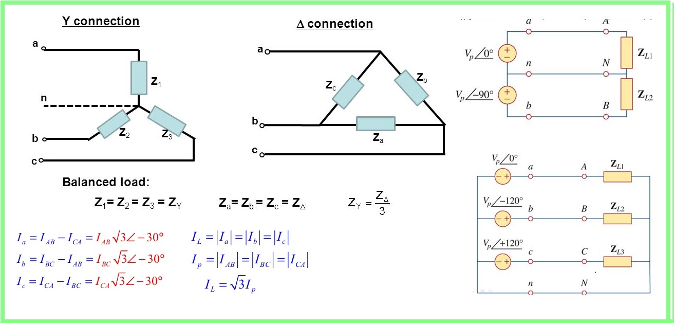
Three phase circuitsPhase circuit system balanced three delta connection analysis loads condition shown below figure Circuit analysis of 3 phase systemWhy three-phase voltage is 440 volts?.

Diy wiring a three phase consumer unit-distribution board and wiring
.
.