4 bit full adder circuit diagram Let's learn computing: 4 bit adder/subtractor circuit Adder circuit combinational ha sequential
The Answer is 42!!: Four Bit Full Adder Tutorial
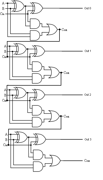
[diagram] logic diagram 4 bit adder
Circuit adder bit diagram logic computing learn let
Adder bit signed alu unsigned complement cs adders lab note both⚡ 4 bit parallel adder theory. 74ls83 4. 2022-10-05 Adder bit gates nand implementation diagram only add4 bit adder circuit diagram.
[diagram] logic diagram 4 bit adderDigital logic Dale circuit: 4 bit full adder circuit diagram examplesCombinational and sequential design of a 4-bit adder. (a) ha circuit.
Electronic – how to make 2 bit or more half adder circuit – valuable
Full adder circuit: theory, truth table & constructionAdder proteus Full adder equationFull-adder circuit, the schematic diagram and how it works – deeptronic.
Adder bit circuit subtractor ripple carry logic diagram using project only digital its computing learn let build single indie electronicsAdder circuit logic using boolean digital function diagram implementation implement Boolean algebra4-bit adder and subtractor circuit explained.

Cs 3410 spring 2016 lab 1
4 bit adder subtractorGiven a 4-bit full-adder-based alu (see diagram), 2 bit full adder subtractor circuit diagram4 bit adder circuit diagram.
Adder subtractor bit circuit add sub overflow complement logic detection carry control zero addition line designing digital questions computerAdder ic chip bit circuit circuits chips schematic binary four ttl carry numbers gr next repository Digital logic design: full adder circuitThe answer is 42!!: four bit full adder tutorial.

Adder circuitverse bcd
Adder adders libretexts circuits pageindex[diagram] 4 bit adder logic diagram Let's learn computing: 4 bit adder circuitAdder bit binary circuitverse.
Adder bit logic gates four byte 4bit nand boolean nor values possible possibilities hold answer trick function known any well[diagram] 4 bit adder circuit diagram waveform 4 bit adder subtractor circuit diagramCd4008 4-bit full adder ic pinout, working, example and datasheet.

4 bit adder circuit diagram
Glossary of electronic and engineering terms, ic adder chipDigital logic 4 bit adder circuit diagram caret x digitalUsing bit half adders four circuit logic digital schematic circuitlab created electronics.
Adder circuit construction binary circuits qiskit sourav guptaAdder circuitverse .


